In Dec 2012, we embarked upon the journey to build a hardware+software startup. Without prior experiences in manufacturing of hardware, both of us thought it best to make full use of our existing skill sets. One of us had been an audiophile for over 10 years, dabbling with DIYs and even writing codes for DSP plugins. So for our first product, we decided to make a high-quality portable wireless speaker.
We are thoroughly thrilled with our final product Blink Speaker - it sounds better than Jambox, Pill, Boombox, and has a great battery life (10 - 30 hours). Most interestingly, its irregularly-shaped design and skin-like texture gives it a unique and mysterious appearance.
Little did we know what hurdles and lessons lay ahead of us in carrying out our project.
Tense. Frustrating. Fascinating. Building a product that functions is relatively easy. Building one that excels is highly challenging. And mass production is orders of magnitude harder.
CHAPTER 1. FROM DESIGN TO PROTOTYPE
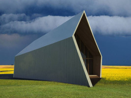
Most of the mini speakers available in the market are simple box-shaped and cylinder-shaped. We wanted to build something different. Inspired by modern architecture, we came out with the irregular polyhedron - it stands out aesthetically while reducing standing waves and hence improving mid-and-low-frequency response quality.
Most producers begin with the PCB (printed circuit board) before moving on to design the outer enclosure box (of a similar shape as the PCB). The reason is plain economics - the process is fast, and the product is easier to assemble. The result: average speakers with plain designs.
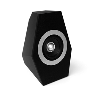
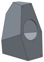
Fig 1. Some inspiration, and our humble first rendering of Blink Speaker
We set about to learn more about manufacturing, including OEM (Original Equipment Manufacturer) and ODM (Original Design Manufacturer). We were clear about the purpose of OEMs - they manufacture varieties of parts for other companies. On the other hand, ODMs can build a product for you even if you know little about the detail. For example, we would need an OEM for our driver unit (if we don't buy an off-the-shelf solution), and probably an ODM for our speaker project to coordinate all the matters (we decided to solve them ourselves).
OEMs are your essential suppliers. ODMs can save you much time and effort, but their work is often mediocre. Many companies, including some well-known brands, outsource product development to ODMs. Little wonder the marketplace is saturated with gadgets which look similar.
We created a simple plan outline: (1) to build the speaker cabinet; (2) to find a great speaker driver unit; (3) to create a high-fidelity amplifier board with wireless input; and (4) to place these components and other accessories (battery, etc.) properly inside the cabinet.
Can you see more detail and steps?
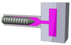
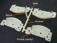
Speaker cabinets are usually in wood (MDF / plywood / bamboo / hardwood / ...) or plastic (ABS / PP / PC / ...). Wood is good for box-shaped and large smooth cabinets, while plastic is more suitable for versatile shapes and accurate features, but requires sophisticated considerations of injection molds, parting and draft.
Take a look at your phone. Chances are, it is made in plastic.
iPhone 4 / 5 are made in steel / aluminum. On the other hand, plastic is better for signal reception.
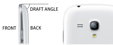
Fig 3. A plastic phone, with the draft angle for back part illustrated
In fig.3 we can see a front part (silver) and a back part (white), separated by a parting line. Each part has its own mold. Look at their curves - they curve inwards instead of going straight down, to provide the very important draft angle, without which the part cannot be removed from the mold smoothly.
The draft angle is usually required to be at least 2 degrees to prevent scratching of the product during the mold removal process.
Meanwhile, iPhone 4 / 5 and Unibody Macs can achieve a sleek straightly-going-down design, because they are milled from metal using CNC (computer numerical control) instead of injection molding. The process is much more time-consuming and expensive. Kudos to Apple.
Turning back to our speakers. Our cabinet would also have a front part and a back part. The driver unit would be attached to the front part. Two problems arise. Firstly, as can be seen in Fig.1, our initial design has a top surface pointing upwards. If we put this surface in the back part, it would become an undercut and blocks the removal of the back part from the mold.
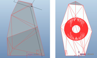
Fig 5. Blink Speaker (still in triangles), the parting line and the undercut (arrow)
As a side remark, mold manufacturer does not use an everyday 3D model in triangle mesh. A common file format is STEP (.stp), generated from professional CAD software, and built upon lines, curves and solids.
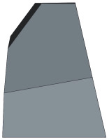
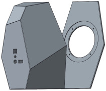
In order to solve the undercut problem (fig 5.), we considered bending a metal plate to form both the front panel and the top surface, but we were concerned that the bending angle might not be as sharp as we desired. We decided to change the design and make the top surface tilt a little bit downwards (fig 7.). The result turned out to be aesthetically more pleasing as well.
Secondly, we needed a method to attach the front part to the back part. Gluing was not a option, in light of vibration from the driver unit. Using screws appeared to be an obvious choice, so we redrew everything in CAD, with six screw holes on the front.
Quiz: does one need to draw the screw threads?
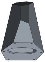
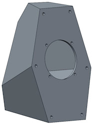
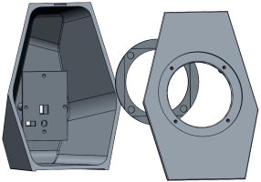
Fig 7. Blink Speaker (now in CAD)
How could we attach screws to the back part? We could add long pillars to the back part (the screws go into them). However, in our case, some pillars would be too close to edges and corners, resulting in deformations when plastic cools down in the mold to form the part.
Special screws with long bolts could also work, but one would have to build extra metal molds for them to customize their dimensions. In manufacturing, every non-standard component has to be molded. It would be wise to keep the number of molds low.
Fortunately, we found an ideal solution in ultrasonic welding, a method that welds plastic parts together firmly like a magic glue. There was a catch - ultrasonic welding was irreversible, so how could the casings be re-opened to allow for repair and maintenance? We had an innovative solution: we would pass the PCB and battery through the front hole for driver unit. Perfect.
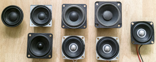
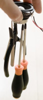
Fig 8. Some of our driver unit samples, and a demonstration of the strength of neodymium magnet
We improved upon the speaker design, adding screw holes for the driver unit, creating a circular slot for a decoration ring to hide these screws, screw pillars for fixing the PCB, and incorporated holes on the back for ports, button, etc.
One needs to think through every bit, and any bit of negligence in design or production might cost you the whole mold. Keeping timely dialogue with suppliers is crucial.
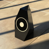
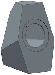
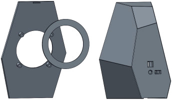
Fig 9. Evolution of Blink Speaker
An accurate cabinet needs to fit everything, which requires us to finalize all components and the interior design as soon as possible. As an example, the PCB cannot be placed at the bottom, because then the pillars for its screw will block the removal of the back part from the mold. As another example, the position and size of all holes have to fit the screws, driver unit, ports, button, etc. perfectly.
Keep in mind that a plastic part will shrink around 0.5% as it cools down in its mold, and its shape will change a little bit, depending on model geometry, material, pressure, temperature, cooling speed and more factors.
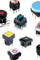
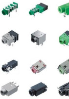
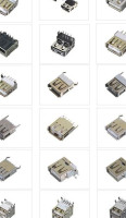
Fig 10. Buttons, jacks, ports
And putting everything together for our irregular-shaped design was like solving a huge jigsaw puzzle. We almost wished we had chosen a box-shaped or cylinder-shaped design, because for such designs everything is straightforward, standard, and less prone to errors: first, make a rectangle-shaped or circle-shaped PCB; second, draw a box or cylinder around it, adding pillars and holes accordingly; done.
Irregular-shaped design later continued to create more problems along the way. The extra effort and cost were well-worth it because the result was a unique speaker that had never been seen before.
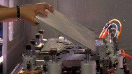
We decided to make a prototype to get a real feel about our design. The traditional prototyping choice is CNC, while 3D printing is the new choice of many. It was fun to watch it in action for the first time.
CNC is more accurate and more expensive, while 3D printing is faster and can be more cost-saving.
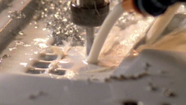
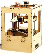
Fig 11. 3D printing is good for rapid prototyping
Seeing our design materialize in reality was exciting. A silly error caught our attention - the front part couldn't fit the back part, as it got mirror-imaged by accident when we parted it. Another problem was the speaker felt out of proportion (too tall), which was more apparent in reality than on computer screen.
We were a bit disappointed about the accuracy of 3D printing - the surface was layered and rough.
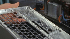
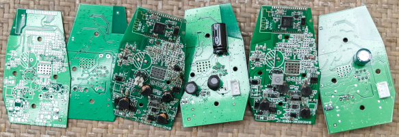
Fig 12. Some of our PCB samples
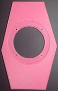
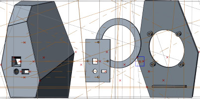
Some errors were less obvious. For example, the four pillars on the back require draft angles. We drew a dummy PCB in our model to make sure the position and size of everything is correct. We also smoothed out every edge and corner of our model, and cut some extra features on the decoration ring to make it fit the driver unit and screws beneath.
Small undercut and missing draft angle can be difficult to see.
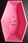
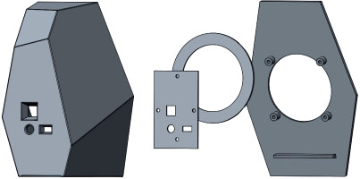
Fig 13. Getting there
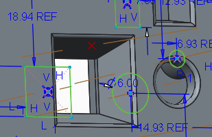
Our final problem was coordinating the PCB and our cabinet. In our design, the button, charging port and AUX input were perpendicular to the PCB (fig.12), but such components were of different heights, so there would be space left between them and the back of the speaker. We came up with a solution (as shown in fig.14) after fixing suppliers for each component, which involved tedious searches.
We spent many hours just searching for an ideal button, which must be small, with LED built-in, responsive, and never gets stuck when you press it.
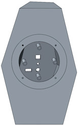
Fig 14. Ready for production, but not end of story
Sending out the final model for making molds required a leap of faith. Although we triple-checked each feature and printed a final prototype to verify the design, we were still nervous that something might went wrong. (To be continued).
To be continued in part 2, where we would meet new problems regarding mold, PCB, electronics, suppliers, and more. It got intense.
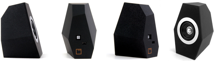
Fig 15. Blink Speaker. Click to learn more about it (with measurement data). We are shipping it globally now.